

HDMI technology has become the global standard for the connection of high-definition equipments. More than 1,700 of the world’s largest consumer electronics, PC and mobile device manufacturers incorporate HDMI connectivity into their products as it delivers both high quality and unmatched ease of use. This project work aims to transmit High-Definition Multimedia Interface (HDMI) and Digital Visual Interface (DVI) data streams to HDMI and DVI capable monitors via Spartan 6 FPGA. The top-level design in this project work displays a simple coloured pattern.
Why should we use FPGA for Image/Video Processing ?
Field Programmable Gate Array (FPGA) are the most appropriate embedded platform for Video/Image Processing. Owing to the parallel architecture, an FPGA is able to perform high-speed video processing such that it could issue warnings timely and provide drivers longer time to response.
Compared to the CPU implementation, the FPGA video/image processing achieves about tens of times speedup for video-based driver assistance system and other applications.
Requirements ?
Hardware Requirements and Software Requirements
- Spartan 6 FPGA
- HDMI/DVI Monitor
- HDMI — DVI Cable (Required for DVI monitor)
- ISE 14.7 Webpapck Design Software
Lets see the working !
Driving DVI/HDMI Capable Monitors to display Coloured bar Pattern
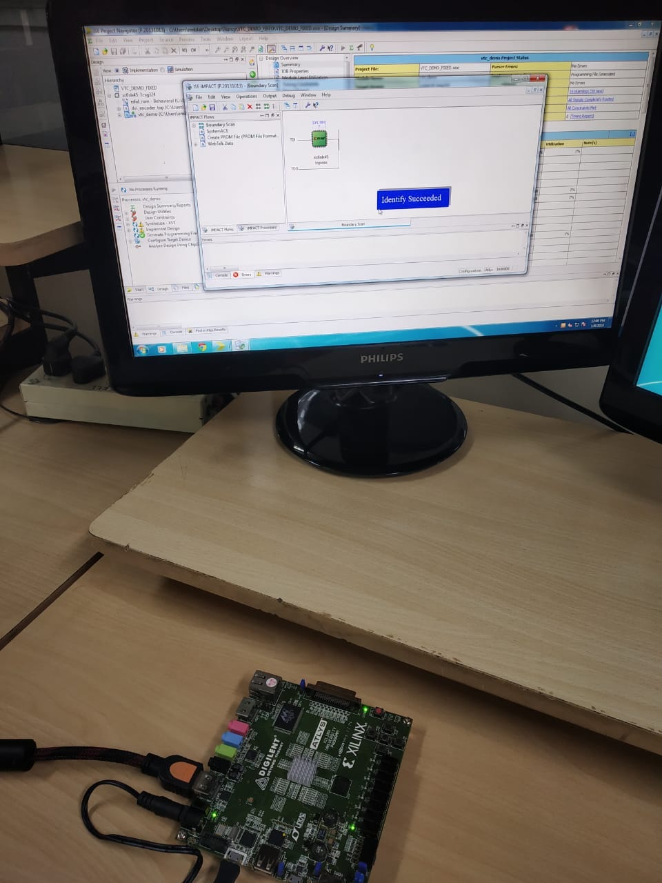
For implementating the Project a new ISE WebPack project is created and all Verilog and VHDL files are added from https://github.com/Nancy-Chauhan/HDMI-data-streams-Spartan-6 .
These files together with other useful files (such as the . ucf file) are included. Then the project is synthesized and implemented. Bitstream file is downloaded to the FPGA board and tested.
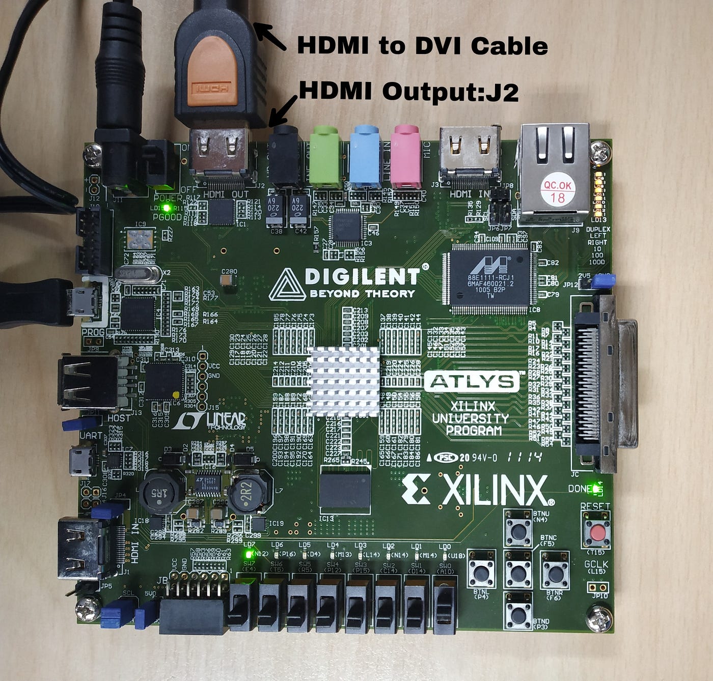
To test the design, we need to attach a monitor to the HDMI OUT (J2) port of the Atlys board. An HDMI monitor can be connected directly using an HDMI cable. To connect a DVI monitor,we need an HDMI to DVI converter.
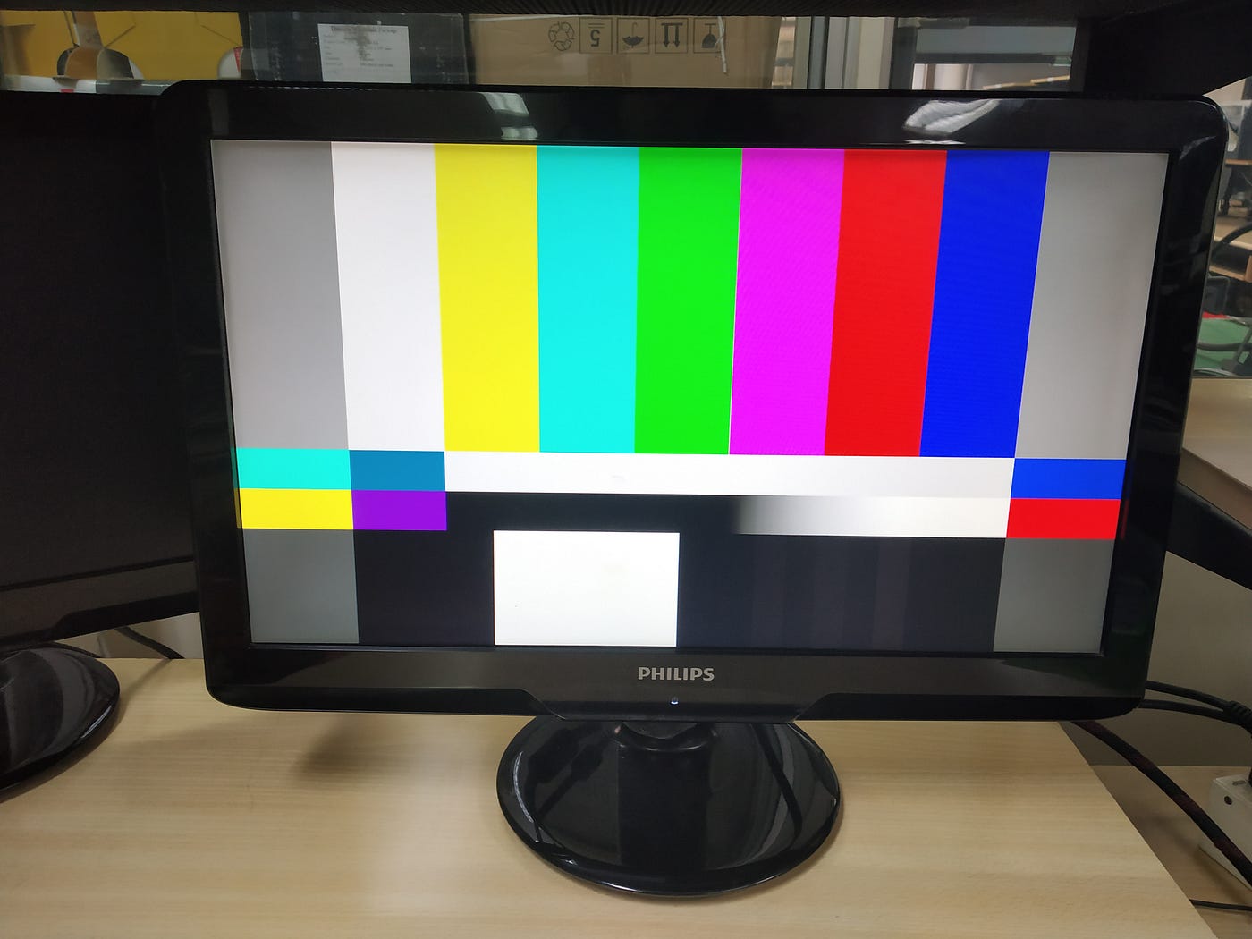
Output
We see the monitor display the coloured pattern as shown in Figure. The monitor shows the default colored pattern without any change in switching configurations. When there is hdmi signal output in HDMI OUT port, LEDs( LD8, LD9, LD10, LD11 , LD12 ,LD13) lights up.

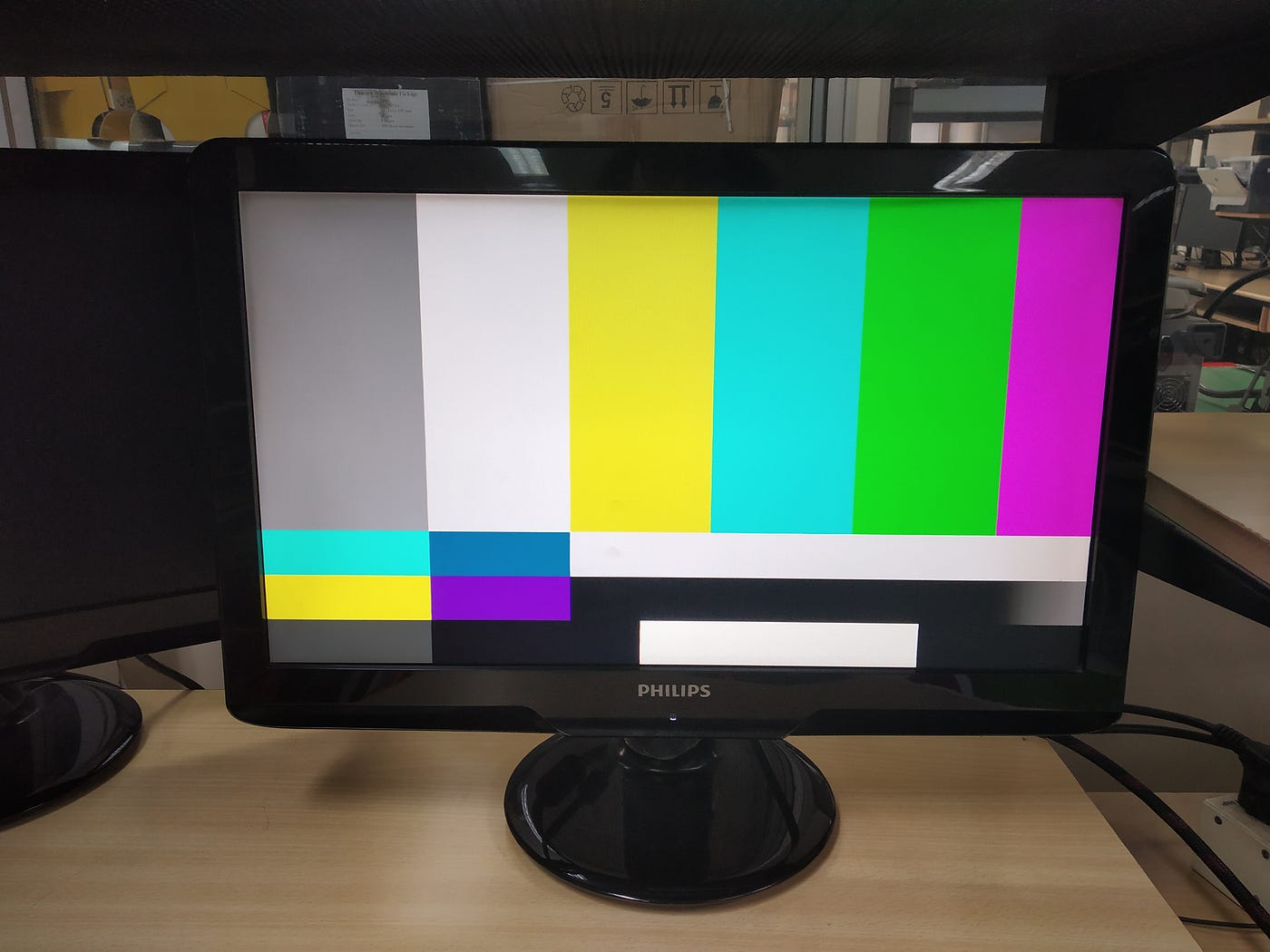
Using three DIP switches on the board (SW0, SW1, and SW3), the user is able to switch among different screen modes. Following test pattern are observed (shown in Figure) by selecting following switches which display 720p frames configurations:
- sw1 = 1, sw0 = 0
- sw2=1, sw1=0, sw0=0
Following test pattern are observed (shown in Figure ) by selecting following switches which:
- sw2=0, sw1 = 0, sw0 =1
Whats happening behind ???
Structure of Project ?
The project work mainly consists of three Parts. In addition, this ISE WebPack project uses both VHDL and Verilog source files.
Reference : Implementing a TMDS Video Interface in the Spartan-6 FPGA — Xilinx
1) Top level design file — vtc_demo.v
2) DVI Encoder file — dvi_encoder_top.v
3) EDID File — edid_rom.vhd
The code : https://github.com/Nancy-Chauhan/HDMI-data-streams-Spartan-6
Problems Encountered ?
While working on Project work, referring project developed by Bob Feng of Xilinx , Implementing a TMDS Video Interface in the Spartan-6 FPGA — Xilinx the following errors are encountered with the Verilog project:
1) Mixing of blocking/non-blocking assignments:
While the Synthesis of the Verilog Project ,the translation process is not followed due to Mixing of Blocking/non-blocking assignment error in the verilog code. This error occurs due to bugs in code.
2) In Spartan-6 FPGA, the BUFIO2 using the DIVIDE(2) applications occasionally enter a stuck state.

3) When the bit file is burned and Connected to DVI Display error message comes on Monitor Screen as shown in Figure . It depicts that the Monitor is unable to recognise the Video Mode Information send by Programmed FPGA

Improved Design ??
The Bob Feng of Xilix design does the bare minimum to demonstrate the HDMI receiver/transmitter concept. It fails to work for most of the time due to EDID issues, and is not completely compatible with modern versions of Xilinx ISE.
1) Fixed mixing of blocking/non-blocking assignments
I have fixed this error by doing changes in code as shown in line 236 of code (shown in figure ). Here non blocking assignment has to be used because it allows to schedule assignments without blocking the procedural flow. The relational operator is changed to remove this error.

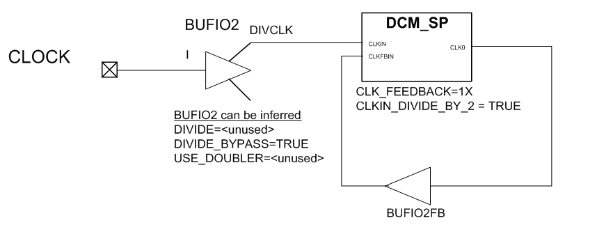
2) Fixed the BUFIO2 divide error
I observed this error occured since this setting is not supported and BUF102 are not compatibile with later versions of ISE. To rectify the Problem , rather than using BUFIO2 to divide the 100 MHz system clock by 2 in Verilog code,I have used a DCM (Digital Clock Manager) to generate the 50 MHz signal
3) Implementation of EDID ROM for both HDMI input
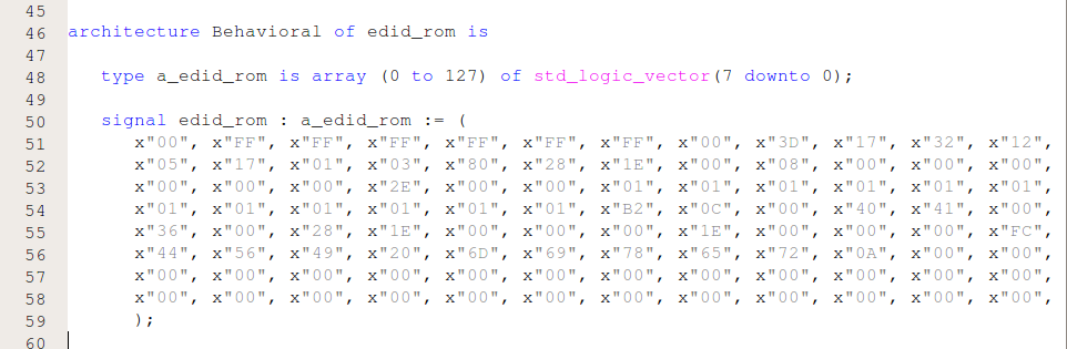
EDID data exchange is a standardized means for a display to communicate its capabilities to a source device. The premise of this communications is for the display to relay its operational characteristics, such as its native resolution, to the attached source, and then allow the source to generate the necessary video characteristics to match the needs of the display. This maximizes the functional compatibility between devices without requiring a user to configure them manually, thus reducing the potential for incorrect settings and adjustments that could compromise the quality of the displayed images and overall reliability of the system.The base EDID information of a display is conveyed within a 128-byte data structure that contains pertinent manufacturer and operation-related data.
What to do next ??
Tansmission of HDMI data streams to HDMI/DVI monitors via Spartan 6 FPGA was succesfully achieved .HDMI Transmitter was implemented,to validate whether the TMDS I/O in the Spartan-6 FPGA is able to transmit video across different screen modes, a colour bar generator is built to work with a dynamically configurable pixel clock.
Further in future various Image/Video processing algorithm can be implemented and observed.

